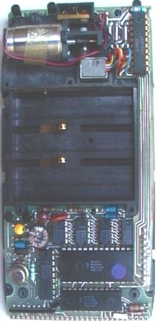
The internal construction of the HP67 programmable calculator is much like the other Classic-series machines, with an internal plastic backbone that serves to hold the Printed Circuit Boards (PCB) and other parts. This can be seen in this picture of the components on the back side of the backbone. In the HP67, the battery pack compartment is in the middle of the machine instead of at the top, which reduces the room available for the main calculator PCB. The main PCB is connected with a set of gold-plated fingers that come from the keyboard/ display PCB and plug from the back into holes along the bottom of the main PCB.
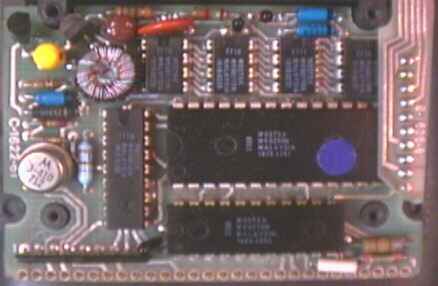
The main PCB, seen in this picture, contains the control ICs, Read-Only Memory ICs, and the power converter that provides the proper voltages for the ICs. In the calculator in the photograph, all of the ICs were manufactured by Mostek, although AMI (American Microsystems Incorporated) was a second-source for most of the ICs. I am unsure of the exact function of the two largest ICs, although I believe the largest (28-pin) IC to be the main controller. The HP Part number for the 28-pin IC is 1820-1751, which also has a Mostek part number of MK6250N. I have seen the same IC used in a HP97. The 22-pin IC below is HP # 1820-1596, Mostek # MK6216N. Although I don't have direct evidence, I believe the 18-pin IC to the right to be the master ROM, with the four eight-pin ICs along the top of the board to be slave ROMs. An article in HP's Personal Calculator Digest said that the HP67 used five ROMs. These five ICs also have the same first four digits in the HP part number. The 18-pin IC is HP # 1818-0268 (Mostek # MK60038N), while the four 8-pin ICs are, from left to right, part numbers 1818-0228 (Mostek MK60171N), 1818-0226 (Mostek MK60172N), 1818-0231 (Mostek MK60176N), and 1818-0232 (Mostek MK60175). I've also seen two of these five ROMs in a HP97.
Note that these ICs were observed in a HP67 with a serial number prefix code of 1706A, indicating production in early 1977. This machine came with an errata sheet that describes some small errors with inverse trig. functions. A later model HP67 dating from 1979 has updated ROMs in place of the 1818-0228 and 1818-0226 ROMs described above, which likely fixed the errata in the later machines.
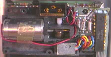
The card reader controller IC and supporting circuitry is mounted on a very thin PCB that runs down the right side of the backbone and plugs into the component side of the main PCB through gold-plated fingers. This close-up picture shows the top of the card reader PCB and the reader mechanism. The IC on this PCB appears to be manufactured by HP, with its part number 1826-0322. This is a different part number from the IC used on the HP65's card reader (1826-0158). This PCB is from a 1977-vintage machine, the design of the card reader PCB was changed later to incorporate a variable resistor for adjusting the speed of the motor, and used a different type of tantalum capacitor than the 1977 version pictured here.
To the left of the driver IC is the rear of the card reader head. Above the card reader head can be seen the troublesome roller that often disintegrates on older machines. The motor is located to the left. The AC adapter terminals and shorting strip can be seen at the top center.
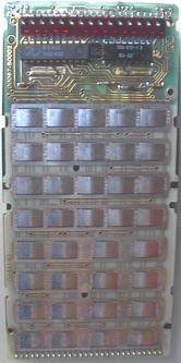
This picture of the keyboard/display PCB for the HP67 shows the arrangement of the LED display modules, driver ICs, and other components along with the keyboard contacts.
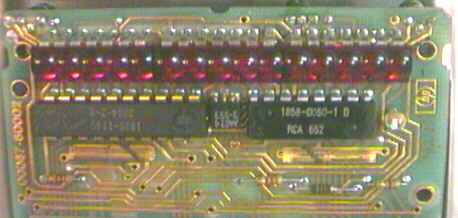
This close-up picture shows the three 5-digit LED modules, HP Part # 1990-0335 (old part number, new part # is 5082-7405) that are at the top of the PCB, with the driver ICs underneath. The 20-pin IC on the left is a HP-manufactured device, part # 1820-1749. To the right is a transistor, and to the right of it is a 16-pin IC. In this particular machine the IC was made by RCA, part # 652, with a HP Part number of 1858-0050-1D. I believe that the left IC is the anode driver and the right IC is the cathode driver. These driver ICs are different from those on the other Classic series machines, possibly because the HP67 does not have the inductor modules for storing energy to drive the multiplexed LEDs that are present on the other Classic machines. To the right of the 16-pin IC is a single LED, which is used to indicate low battery (unlike the other Classic-series machines, the HP67 did not light all the decimal points on a low battery condition).