RetroBrew (nee N8VEM) Single-board Computer
The N8VEM (now renamed "RetroBrew Computers") is a series of home brewed single-board computers generally in the Eurocard format. It is made in the style of vintage computers of the mid to late 1970's and early 1980's using a mix of classic and modern technologies. It's designed with DIP chips rather than SMT components and largely uses parts that are readily available.
There are too many PCB types and variants to list, but the home page is here and you will find links to schematics, documents, software and a message board. It also has a link to the Wiki, which is the project knowledge base.
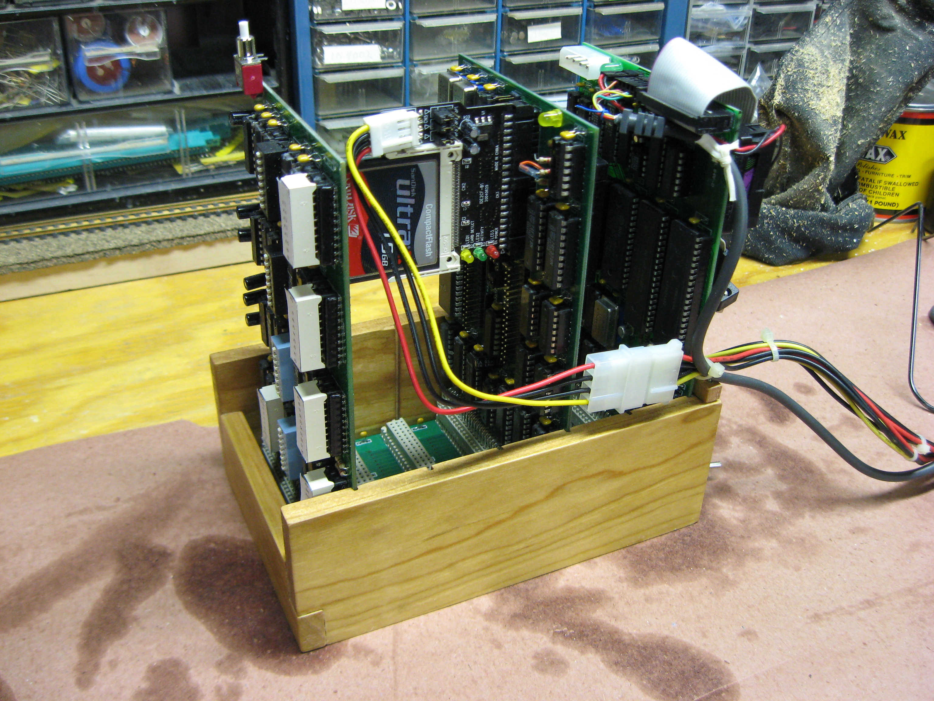
The first one I built was the Z80 board and related peripherals (shown below), and then I built the 80C188-based SBC-188 and related boards (SD-card storage and 4MB or RAM), followed by the 68008 "Mini68K" board. The boards are fairly dense, but easy to assemble. In all, I probably have 15 boards of various types (3 CPU boards, a few memory boards, three video boards and many peripheral boards). They're a lot of fun to build and work "right out of the box" as they say.
Z80 System
Here are a few pictures of the base Z80 setup (click to enlarge):
- Picture 1: Bare card cage made of cherry.
- Picture 2: Populated card cage, right-hand side.
- Picture 3: Populated card cage, rear.
- Picture 4: Populated card cage, left.
1:
2:
3:
4:

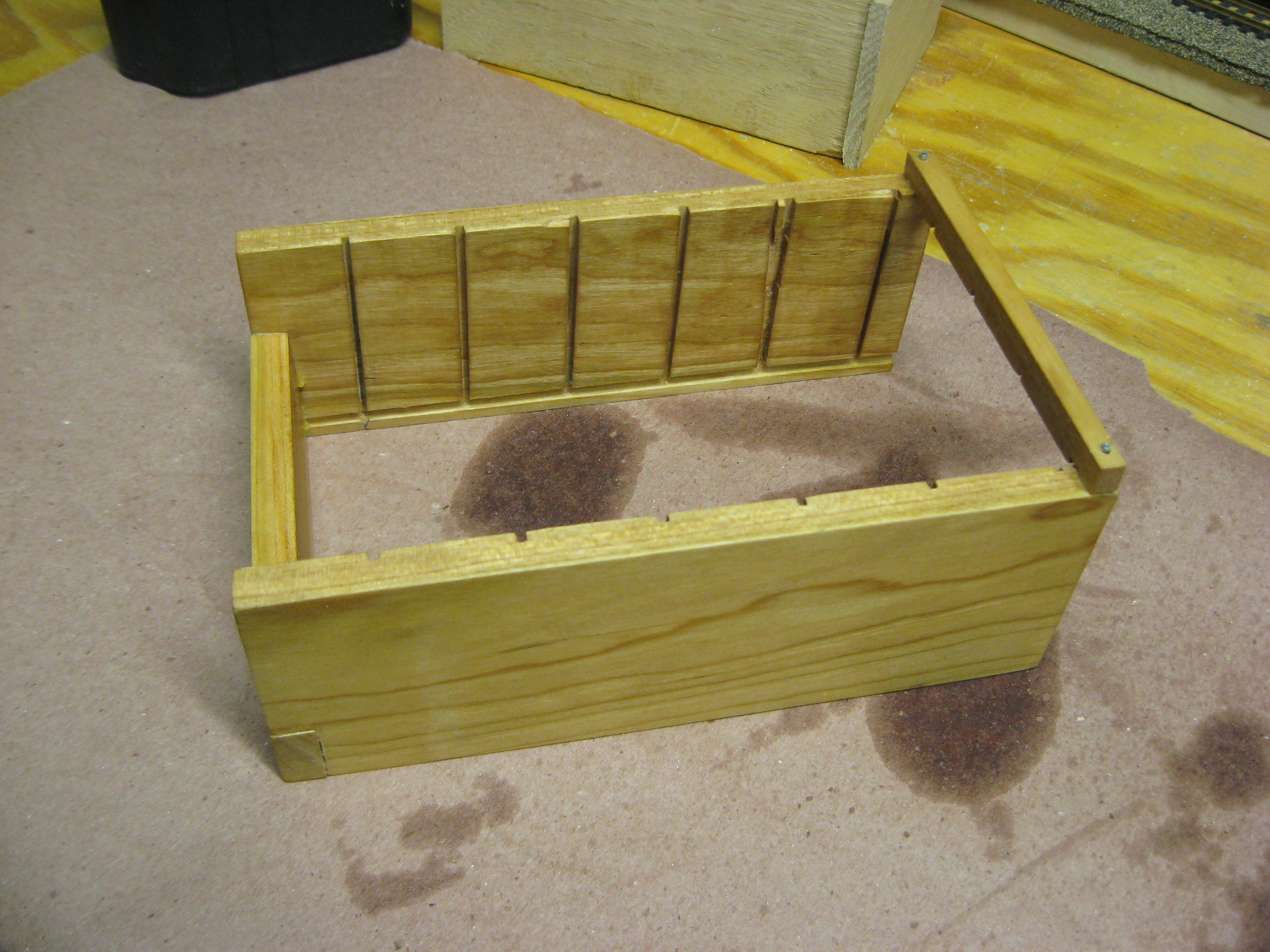


I didn't design this cage with any formal plans in mind. But after I posted these pictures to the N8VEM list, I was forced to create an ex post facto design document.
I had in mind something like the SOL-20 or the Northstar Horizon when I did this -- two vintage machines that mixed wood and machinery successfully (although the Northstar used plywood).
The wood is clear cherry 2-1/2" (nominal) wide by 3/8" thick
by 2' long (the length was the shortest I could by). A good local specialty
lumber yard should have this. I actually got my wood on
http://www.hardwoodboardsource.com/ because I was too lazy to drive to the
specialty lumber mill that's about 15 miles away. The order came in a couple of
days by UPS and required no prep work to use. I also considered using walnut,
which I've worked with before. Mahogany is another good option.
The sides of the cage are just
under 7" long. The overall outside width is 4-9/16" and the inside width is
3-13/16". I tried to size it to provide adequate clearance in the front for the
buss monitor card. The short board in the front is 1.45" high so that the top of
it comes just below the LED bars. The little bar in the back is there just to
keep the top of the cage from splaying outward.
The backplane sits in a groove
that's 1/8" from the bottom of the board. The groove is 1/8" wide by about 1/16"
deep. Similarly, the card guide groove is 1/16" wide by about 1/16" deep. The
cards are spaced 1-1/8" apart on center, with the first one starting 1-1/32"
from the front. The last one
should be about 1/2" from the back.
After routing, the grooves need
sanding with a file or emery board in order to widen them slightly so that the
cards slide smoothly.
The groove router bits I used
were flat-bottom 1/16" and 1/8" wide (1/4" shank) and made by Freud. They're
available from Amazon (and I'm sure other places as well). Even though the
router was mounted in a router table, there was some creep resulting from the
pull of the router. You have to keep a very tight grip (or use finger boards)
and keep the wood blank square in order to route the side groove perfectly
perpendicular to the backplane groove.
I sanded the wood and then
finished it with two coats of boiled linseed oil. After the second coat dried
(leave each coat overnight to soak in, with a light sanding with 400 grit
sandpaper in between each coat), I finished it off with a coat of Minwax
finishing wax. This results in a simple and durable finish that highlights the
grain and brings out the warmth of the wood.
If using linseed oil, exercise
great care when disposing of the rags -- they can spontaneously combust if
there are too many of them together in the garbage and they're not totally dry.
The only thing I have left to do is to glue some kind of insulating sheet over the bottom of the backplane. Even though the bottom of the board is 1/8" above the bench, all you need is one screw floating around and it's lights-out.
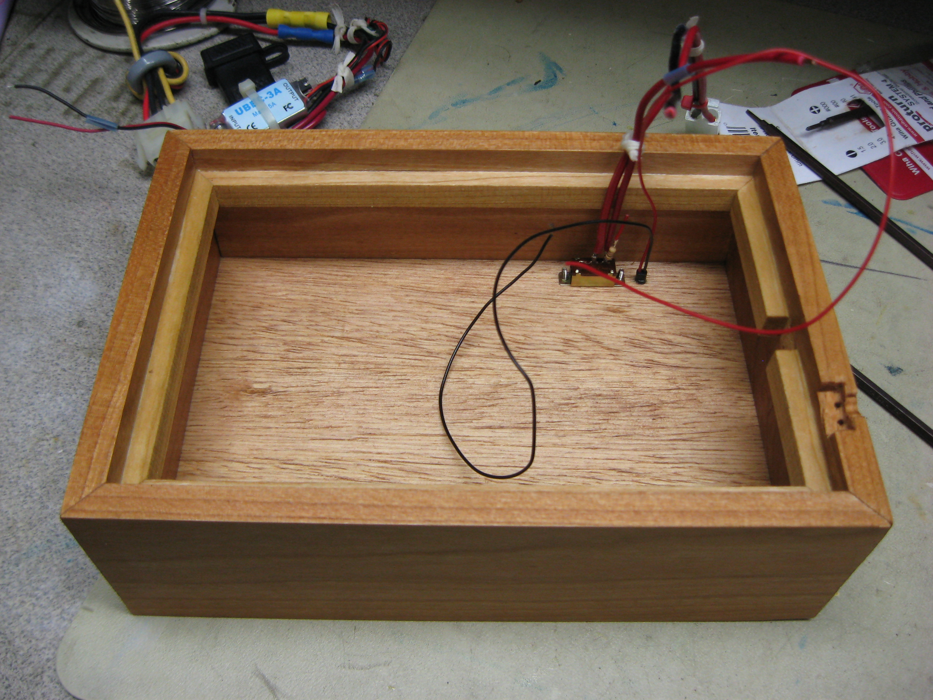
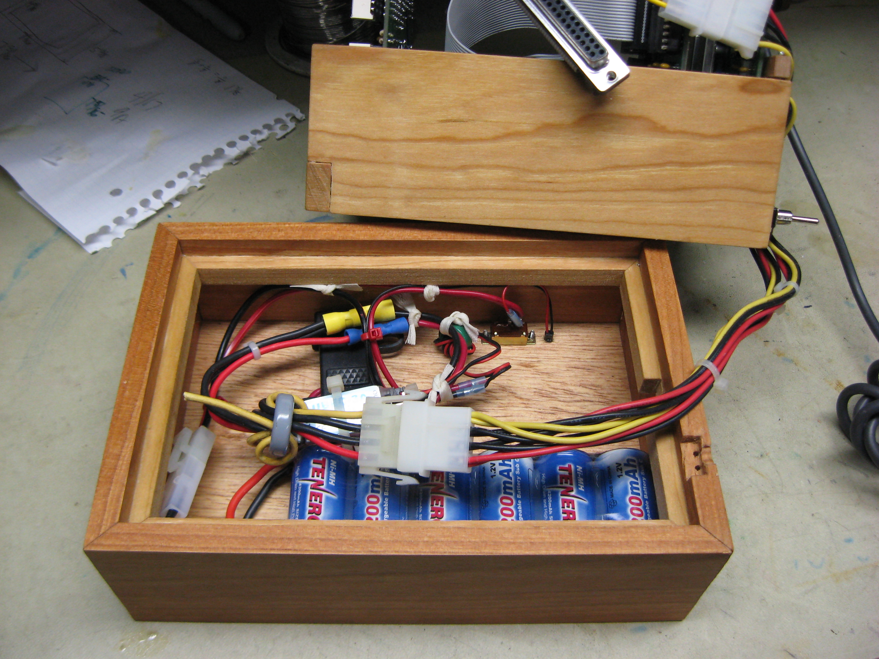
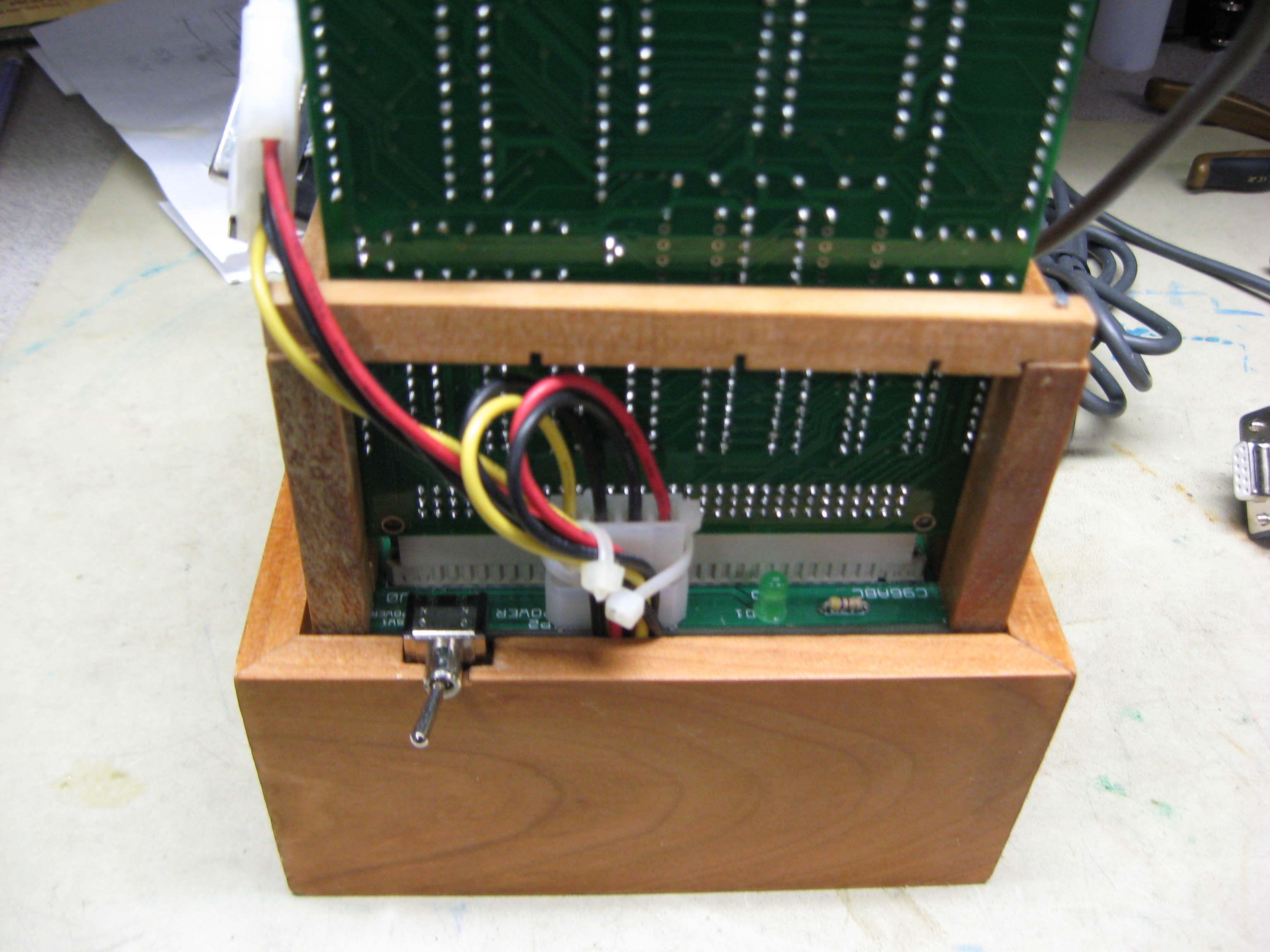
I have also built a battery pack so I can run this off-grid. The CPU card cage sits in another box also made from cherry. This box contains a 7.2v/4200mAh high-capacity NiMH R/C battery pack, an ATC automobile fuse and a 5v/3A switching regulator (originally a battery eliminator for a R/C plane) and a power switch.
I used the same 2-1/2" x 3/8" clear cherry as I did for the card cage. The outside dimension is 7-13/16 x 5-3/8", which results in an inside dimension of about 7-1/16" x 4-5/8". To the inside I glued a 1/4" x 3/8" strip of cherry about 3/8" from the top and on which the CPU card cage will sit. I had to cut a notch in one strip to accommodate the power cables, and another in the end for the backplane power switch. I routed a 3/16" groove 1/4" from the bottom to accommodate a piece of 3/16" plywood which acts as a bottom. Again, it's finished with a linseed oil finish and sealed with wax.
The battery pack came from All-Battery.com (http://www.all-battery.com/) and the BEC came from a vendor on eBay (search for "Viverrine UBEC 3A 5V/6V Output 5.5V-28V Input 2~6s LiPo"). The switch, LED and Tamaya connector I had in the junk box.
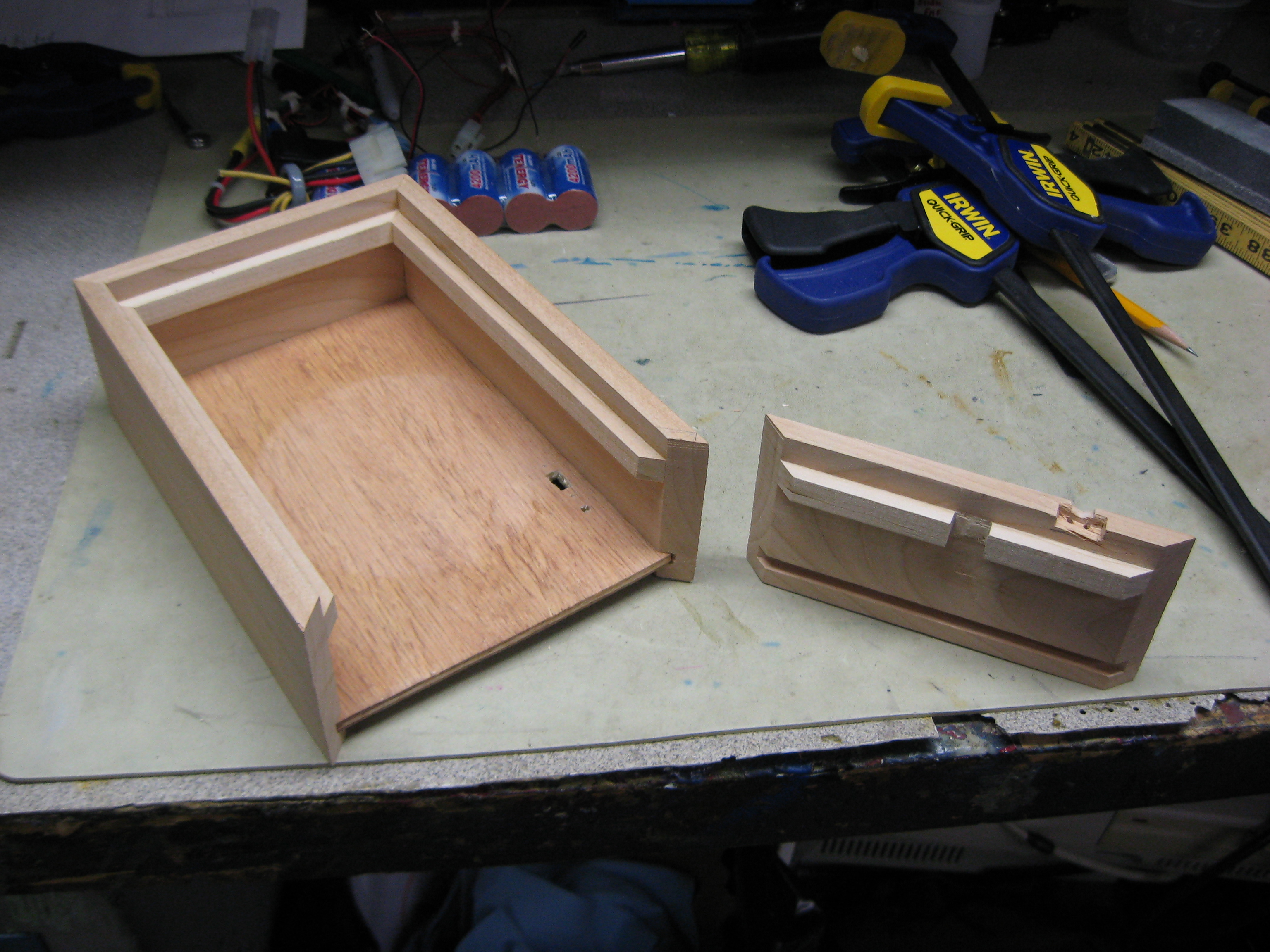
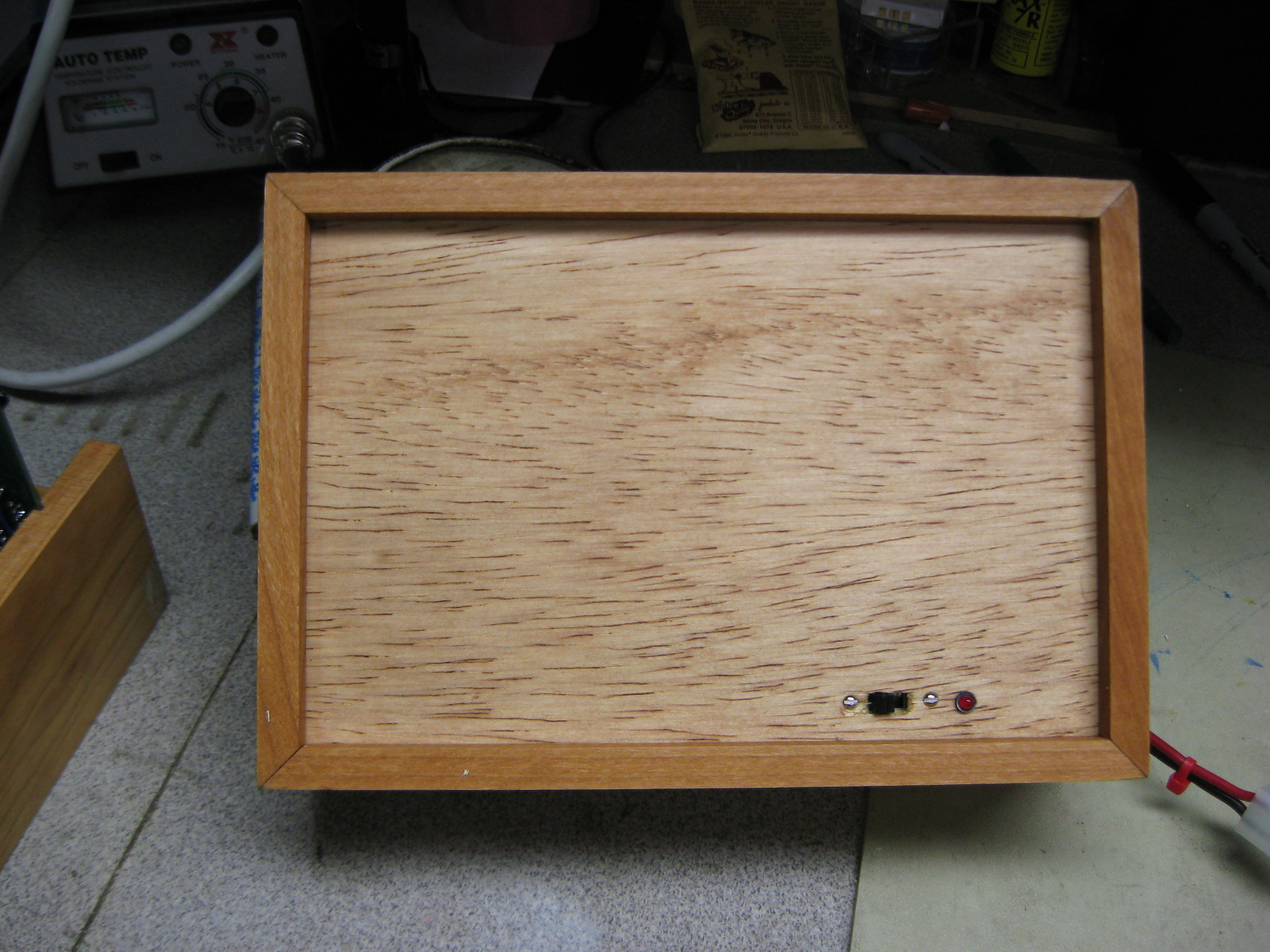
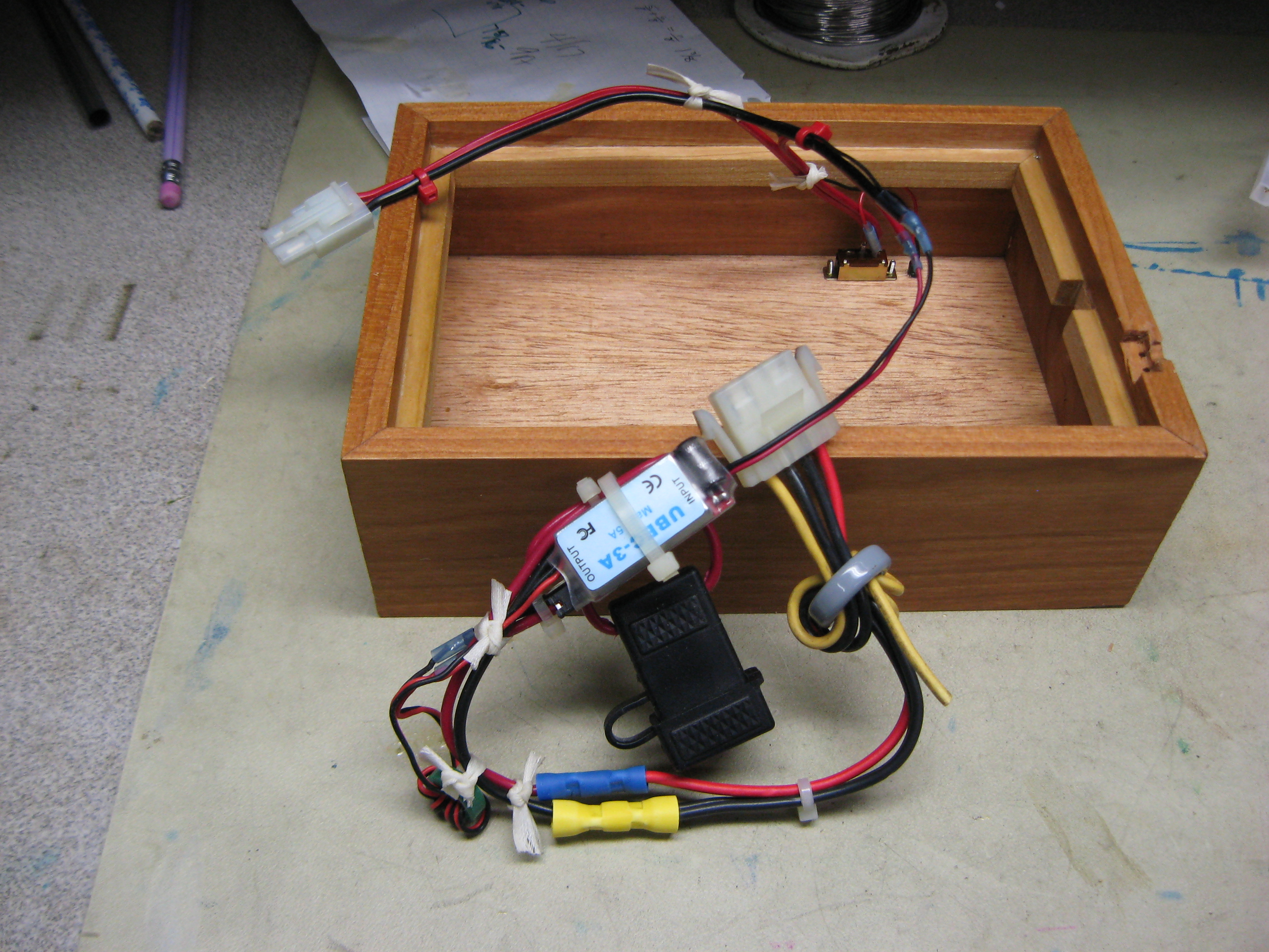
Here are a few pictures of the base setup (click to enlarge):
- Picture 1: Case sides showing the ledge at the top and the groove at the bottom.
- Picture 2: Partially-assembled case.
- Picture 3: Partially-assembled case.
- Picture 4: Fully-assembled case with a view of the power switch.
- Picture 5: View of the bottom with a view of the power switch.
- Picture 6: Assembled and wired power assembly. The black rectangle is an ATC automotive fuse holder with a 3A fuse in the input. The silver rectangle is the switching regulator. Since the N8VEM uses standard IBM-PC floppy connectors, I terminated my power supply with a connector from an old PC power supply.
- Picture 7: Finished power supply assembly.
- Picture 8: Finished stack, front view.
- Picture 9: Finished stack, rear focus view. This shows how the cable enters the battery box and the carvings in the top to accommodate the backplane power switch.
1:
2:
3:
4:
5:
6:
7:
8:
9:

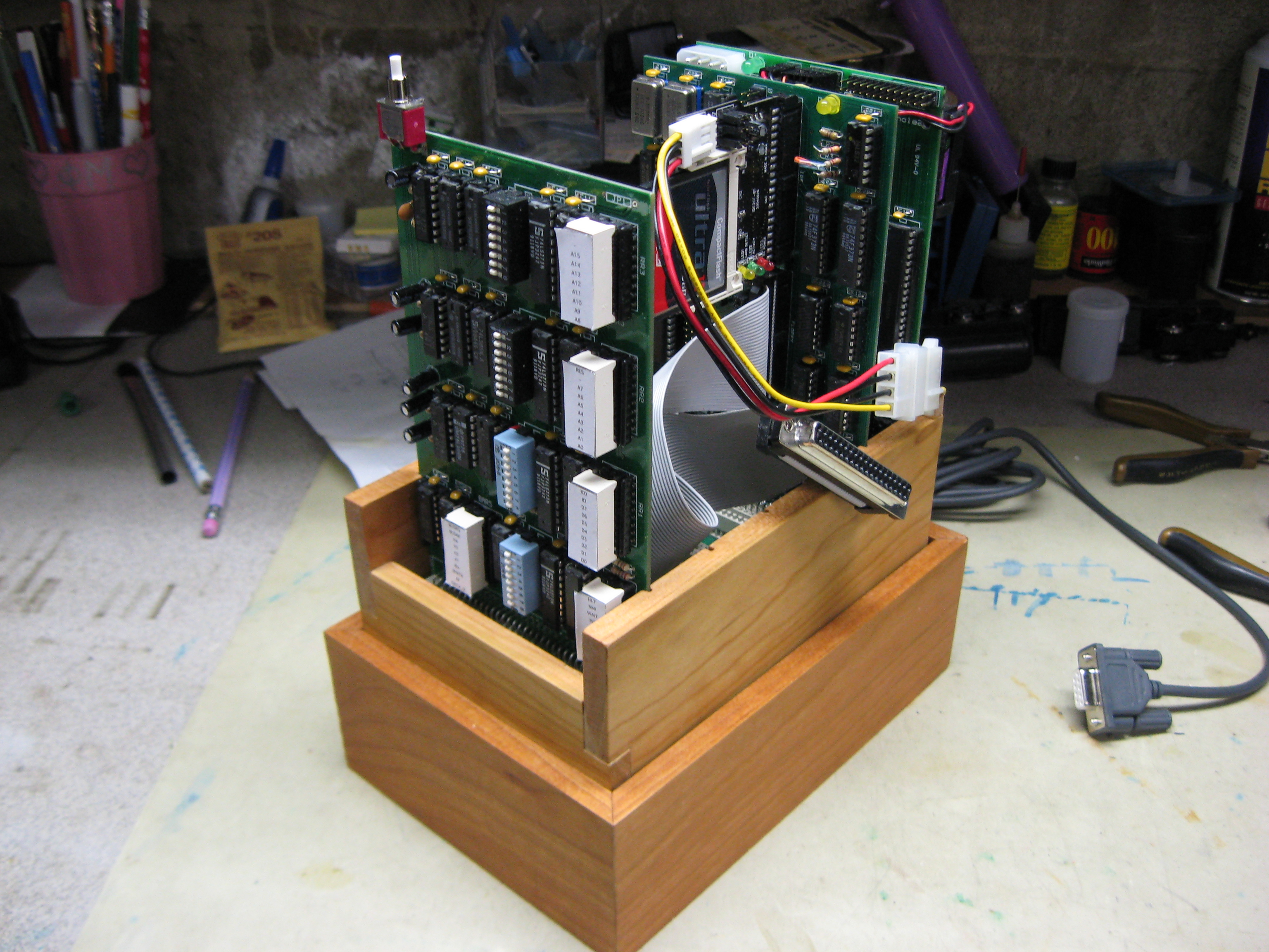
You will notice in Picture 8 that the LED bar graphs are covered with paper labels. This card is the ECB Bus Monitor. It allows you to set breakpoints and see the status of the address and data busses as well as the CPU status. I created labels in Excel which I glued to the top of the displays so that I knew which LED meant what. Here's the spreadsheet (XLS).
BBSing
One of the things I want to get the N8VEM to do is set it up as a vintage bulletin board server, mostly as an experiment. The added twist here is that rather than using a regular 300 baud modem and a POTS connection, I wanted to serve over the Internet. In order to get this to work on the N8VEM, you need a few things (well, more than a few):
- N8VEM Zilog Peripheral Board - this has the Z80-DAR/T serial port needed to connect to the computer that will act as the modem bridge between the Internet and the N8VEM (the serial-Ethernet bridge).
- A spare PC running some later form of Windows and on which the bridge software is going to run. The PC needs a fixed IP address rather than one issued through DHCP.
- A serial null-modem cable to connect the J3 of the N8VEM Zilog Peripheral Board to a spare serial port on the bridge PC. This Excel spreadsheet contains the hook-up diagrams for the cables. The connector on the PC end should be a DE9F.
- The Telnet BBS modem emulation software by Leif Blumquist (http://home.ica.net/~leifb/bbs/). Don't download the version on Leif's site if using the old-school CP/M-based "BYE" remote console program. BYE does not understand the verbose Hayes response strings sent by the TelnetBBS program. I have a specially modified version here that supports the proper numerical response codes expected by BYE.
- An internet connection with the telnet port (23) opened and ultimately pointing to the IP of the PC being used for the serial-Ethernet.
- If your external Internet address is dynamic (like mine is on Cablevision's Optimum Online service), you will need an IP mapping service like DynDNS. Their small utility program that runs on a computer inside your firewall maps your changing external IP address to a static host name. Mine is n8vemrac.servebbs.net.
- The BYE remote console program. This can be downloaded from the BYE5 folder on the Walnut Creek CD-ROM archive at Retroarchive.org. This zip archive contains a working version of BYE for the N8VEM with the Zilog Peripheral Board at the default I/O ports.
- A BBS program. I'm using RBBS from the Walnut Creek CD-ROM but others will work so long as you modify the options in BYE accordingly. Instructions in BYE are included how to do this. You can use my version as a guideline.
- A CP/M emulator such as MyZ80, available on the Walnut Creek CD-ROM (mirrored here). This is used to recompile BYE5 using ASM for CP/M.
- A standard CP/M CBIOS. This is the biggest point. What makes BYE work is that it locates the CBIOS function jump table and re-maps the console routines to its own routines so that it can redirect the traffic over the modem. Think of it as a program that enables you to remotely access CP/M over a modem -- just like the Windows "remote desktop" but more primitive. This zip file contains the ASM files needed to build a ROM for the N8VEM that works with BYE. It took me weeks of troubleshooting before I discovered that the original code was "non-standard" enough that it wouldn't work remotely even if it worked locally.
Here's how this setup works. There are three significant pieces -- the vintage computer (in this case, the N8VEM acting as a BBS host), the bridge PC, and the remote computer (acting as the BBS "caller
The bridge PC running the TelnetBBS Server acts as a modem emulator. To the vintage computer connected to the bridge PC's serial port, the bridge PC looks like a Hayes-compatible "intelligent" modem running at 9600-baud (a comfortable speed, although it can be set for faster). The other side of the bridge is connected to the Internet and acts as a remote telnet server. TelnetBBS manages the traffic between the serial and Ethernet connections and emulates the Hayes command set for the vintage computer.
The vintage computer connects to the bridge PC with a regular null-modem cable. Using one of the test programs for the Zilog Peripheral Board, and Hyperterm on the bridge PC, you should verify that the cabling is correct. BYE5 runs on the vintage computer and monitors the serial port looking for the "ring" code from the TelnetBBS program. When it receives it, it will jump into action by answering the modem to complete the connection, and then chaining execution to the BBS program.
The BBS "caller" uses a regular telnet application to "dial" the host BBS. When the TelnetBBS program receives an inbound connection, it completes the connection on the telnet side but "blocks" as it begins simulating handling of an incoming call by a Hayes modem. TelnetBBS sends a "ring" response code to the vintage computer. Seeing this, BYE responds with "ATA" to answer the call. TelnetBBS then unblocks the telnet connection and returns "CONNECT" to BYE. At this point, the end-to-end connection is complete and data can flow. BYE then chains execution to the loaded BBS program (RBBS in my setup) which takes it from there.
BYE5 Configuration
Setting the BYE options is actually almost the easiest part because the instructions and the comments in the code are pretty clear. As mentioned above, the base BYE program requires hardware-specific "inserts" to be useful. The first insert is for the serial port hardware and the second is for the real-time clock.
The BYE distribution archive has two files which summarize the available insert files and the code tells you where to insert them. Once you find a hardware support insert that matches (or closely matches) the hardware on which BYE is running, you just need to make the appropriate changes for I/O ports and status bit positions. Finally, you re-compile BYE using ASM for CP/M (and hence the need for the CP/M emulator).
I didn't add RTC support yet, so I didn't add that insert. For the serial support, I could only find a hardware insert that was close because in 1981, no N8VEM existed :-) The Ampro LittleBoard is the closest (DAR/T with fixed baud clock). I only had to change the I/O port assignment and the status bit, and I was good to go.
Configuring the Bridge PC
I used a spare Mini-ITX PC running Windows 2000 for this project. It's a standard, fully-patched PC with anti-virus and firewall software. You need to use a static IP for the PC so that the router can route the port 23 traffic. Write this address down as you need it for configuring the router and TelnetBBS.
Configuring the Router
Most home routers (such as Netgear, D-Link and Linksys) are NAT (network address translation) routers with two Ethernet interfaces. They route Ethernet packets from the external dynamic IP address to the non-routable "internal" addresses (such as the Class C network addresses beginning with 192.168.x.x). To serve a BBS from behind a NAT router, you need to enable "port forwarding" for Telnet (port 23), and forward the traffic to the IP of the TelnetBBS bridge PC.
Port forwarding is a static routing rule -- when the router sees traffic of a specific type (like telnet traffic), it will route it to the specified internal address. This is why the bridge PC we're using for this project needs to have a static IP. Refer to the manual for your router as to how to open an external port and have it "forward" to a specific address.
Because of this address translation, unless you keep track of the IP address the ISP assigns to you, there is no way for someone to "call" your BBS. This is where a free dynamic DNS service (such as DynDNS) can help. It uses a little applet on your PC to keep track of the IP address assigned to you by your ISP. It then maps this address to a static host name like "mypc.host.net" which you can use to access PCs connected to your router.
TelnetBBS Configuration and Settings
There is no installer program for TelnetBBS so just create a folder for it and unzip the contents of the archive into the folder. Depending on your system, you may need to install the VisualBasic 6 runtime module, which is available from Microsoft.
Follow the directions in the TelnetBBS manual for setting the IP address and serial port. The IP address is the address of the PC acting as the bridge (such as 192.168.1.20). The value for the COM port is the number of the port - "1" for COM1, etc.
Most of the default options in the tabs are appropriate, with the following exceptions beyond the defaults. The INI file in the ZIP archive posted here is pre-set for these but double-check just in case.
- COMMS: Set the port for 9600,8N1; use the standard TelnetBBS cable (option 1); hardware flow control; enable ATE1 command echo.
- CONNECT: raise DTR when caller connects; wait for BBS to send ATA; send "RING" to BBS.
- DISCON: disconnect if BBS drops DCD; disconnect if BBS drops DSR; disconnect on +++ATH; auto-disconnect; send "NO CARRIER"; lower DTR.
- DIAGS: it's up to you how much logging you do. I have detailed logging enabled so I can see everything that's going on.
- EMU: allow outgoing calls; send string on telnet connect "1"; enable "Hayes" emulation.
Problems Encountered
There were two significant issues I encountered while putting this together, one related to BYE and one related to the version of CP/M running on the N8VEM.
Status Bits When I added the hardware insert for the DAR/T, the code defaults to checking for the carrier using CTS. CTS is connected to RTS in a NULL configuration but that isn't active before a call connects. If you change the status sense to DCD, it works.
CP/M BYE is a console redirection program. When the call connects, it patches CP/M's CBIOS function jump table for the reboot functions and the console functions (in, out, status). The jump table must contain only jumps (i.e., "JP WBOOT") and nothing else because BYE writes the addresses of its own handler routines into this table. Also, BYE relies on the address at $0001 (the warm start vector) to locate the table and navigate to the routines it needs. If you're building a CP/M system from scratch and adhere to the CP/M Alteration Guide, you should be OK.
System-related Articles
Here are a few articles from BYTE Magazine that might be helpful to builders:
- High-Resolution Sprite-Oriented Color Graphics (Steve Ciarcia; BYTE 8/82, p.57)
80C188 System
The SBC-188 system is a great system to play with. It runs MS-DOS (I'm running MS-DOS 6.22) but in the base configuration (CPU and disk), it can only use character-mode (i.e., STDIN, STDOUT) applications. Fortunately I found a copy of MS-BASIC (v5.28) that will work. Grab it here. It's the same one I use on my Seattle Gazelle (which runs MS-DOS 1.25 or 2.0).
My system consists of the CPU, the Dual-SD storage card, the new VGA3 card, and a serial/parallel card I designed. The SBC-188 includes a floppy controller (which I have used to bootstrap the SD cards, but I have no drives currently installed). Before the Dual-SD card was available, I used both the Parallel Port IDE interface and the DiskIO board which has both floppy and IDE interfaces.
The newest board I built for this is the VGA3 board, which has a standard PC-style VGA controller and PS/2 keyboard interface. I also have the CVDU board, which is a color character board based on the Commodore 8563 video controller. It's painfully slow, unfortunately, and outputs video at a non-standard scanning rate (thus needing a special monitor). The VGA3 works well for this system and is highly compatible, being based on the 6445 CRT controller. There are some slight screen artifacts on refresh, but otherwise works great.
To go along with this system, I designed and built a dual serial/parallel interface card (link). It uses a high-integration peripheral chip from Texas Instruments to provide two PC/AT-compatible serial ports and a Centronics parallel printer port -- I/O options that have always been lacking on this system. The BIOS for this system is partially PC-compatible but only has stub routines for INT14H (serial) and INT17H (printer) calls. So, I adapted two TSR drivers (one found on Simtel and one in a DOS Drivers book) to provide an environment such that MS-DOS will work with the ports. That was a fun experience -- I learned just how little I know about x86 programming doing that project, but it works, so that's good.
Copyright (c) 1998-2023 Richard A. Cini, Jr. (rcini at msn dot com) All Rights Reserved. All copyrights of any third parties referred to herein are hereby acknowledged. There is no warranty, either express or implied, relating to any of the content contained herein. The site maintainer shall in no event be liable to anyone for damages, including any loss of profits, lost savings, or other incidental or consequential damages arising out of the use or misuse of the information contained on this Web site. Batteries not included. You may use the information contained herein for NON-COMMERCIAL purposes only and AT YOUR OWN RISK.
Last updated 2023-02-12 12:56 -0500