Singer System-10
Being designed in the US, this machine wouldn't normally rate a place on this page. However it is so unusual
that it deserves mention somewhere on the Web, and no-one else seems to have done so. So here it is. This
is put together from memory, so there may be errors. Corrections & additions are welcome.
Cover of a Singer-10 manual
Architecture
Designed in the late 1960's, the S-10 (as it was known) can trace its parentage to the IBM machines
of the day. It was designed for commercial EDP work. There was an RPG-II compiler, although the company I
worked for used assembler exclusively.
Characters
The S-10 had a byte (or "character") length of 6 bits, the internal character code being equivalent
to ASCII characters 0x20..0x5F, with 0x20 subtracted, so mapping into the values 0x00..0x3F. Multi-character
numbers were processed by repeated CPU cycles.
The 6 bits of a character were referred to as 1,2,4,8,Y,Z, corresponding to the ASCII binary weights
1,2,4,8,16,32 respectively. ASCII bits 32 and 128 were discarded in the conversion.
Number Representation
The S-10 was a big-endian machine, with the most-significant character of a multi-character number stored
at the lowest of a contiguous range of addresses. Negative sign was flagged by setting the Z bit on the
least-significant digit, so mapping 0..9 to P..Y. For all valid digits, the Y bit is set to 1. It follows
that there are two valid representations of zero: '0' and 'P'. The numeric instructions treated these
identically (apart from the sign).
Memory Addressing
A hardware switch-panel assigned memory in blocks of 1000 characters, to up to 20 "partitions", plus a
common area. There was a 1:1 correspondence between partitions and concurrent tasks. The physical memory
ranged up to 65536 characters, rounded down to 65000, since memory was partitioned in 1000-character blocks.
Memory addresses were signed decimal numbers, ranging -9999..+9999, with separate -0 and +0 values.
Positive memory addresses point into the current task's partition, while negative numbers point into the
"common" area, shared by all partitions.
Partitions were of 2 types, user and blind. User partitions were controlled by a human
interface, ie a keyboard or video terminal. Blind partitions were controlled indirectly, by commands issued
from a user partition. Blind partitions were often used to support shared printers, modem interfaces, etc.
They could also be used to run background tasks.
The above applies to both Model-20 and Model-21 CPU's. The Model-21 could address extended memory (above
9999), by setting bits in the 'Y' row of a memory address to zero. The resulting Y fields were complemented,
and the result taken as a binary base-value, scaled by 10,000. (This was the only use of binary notation in
the machine.)
Memory was ferrite-core, with a cycle time of 3.3uS. With a character-serial architecture, it therefore took
33uS to fetch an instruction. There was no pipelining (since almost every function involved a memory access,
there was little opportunity).
Address Indexing
Each partition had a set of dedicated memory locations (in its partition area), which provided 3, 4-character
index registers (X1,X2,X3), a condition-code register, and a buffer address and count used by the I/O
instructions. If the index field (AX, BX in the tables below) was set to a non-zero value, the index register
was added to the corresponding memory address. In the following instruction descriptions, the term "address"
includes indexing where appropriate.
Instructions
| Char |
0 |
1 |
2 |
3 |
4 |
5 |
6 |
7 |
8 |
9 |
| Z |
OPCODE |
AS |
AX |
BX |
BS |
| Y |
1 |
1 |
1 |
1 |
1 |
1 |
1 |
1 |
1 |
1 |
| 8 |
LA
Cond. |
A0
(ms) |
A1 |
A2 |
A3
(ls) |
LB
Cond. |
B0
(ms) |
B1 |
B2 |
B3
(ls) |
| 4 |
| 2 |
| 1 |
All S-10 instructions were 10 characters long, aligned on a 10-character boundary. The format of instructions
is shown (Model-20 CPU).
Each instruction comprised two memory addresses (address, sign, index
register), two length values (LA, LB, range 0..9, where 0 denotes 10), and the operation code. In general,
these are the source and destination, or operand-1 and operand-2 / destination.
Operations
| Operation Codes |
| 0 |
0000 |
R |
Read from disk/partition |
| 1 |
0001 |
W |
Write to disk/partition |
| 2 |
0010 |
AA |
Add address (S25) |
| 3 |
0011 |
MA |
Move address |
| 4 |
0100 |
A |
Add |
| 5 |
0101 |
D |
Divide |
| 6 |
0110 |
M |
Multiply |
| 7 |
0111 |
S |
Subtract |
| 8 |
1000 |
MC |
Move characters |
| 9 |
1001 |
MN |
Move numeric |
| 10 |
1010 |
SM |
Set mode |
| 11 |
1011 |
BC |
Branch conditional/ Link |
| 12 |
1100 |
E |
Edit (ie output conversion) |
| 13 |
1101 |
FN |
Form numeric (ie input conversion) |
| 14 |
1110 |
C |
Compare |
| 15 |
1111 |
X |
Exchange |
| Branch Conditions |
| 0 |
Never (ie NOP) |
| 1 |
Lower |
| 2 |
Equal |
| 3 |
Higher |
| 4 |
Overflow |
| 5 |
Always |
| 6 |
Store link: don't branch |
| 7 |
Service Request |
| 8 |
Branch & yield |
Read from Disk or Partition From disk, read a fixed block of 100 characters (1 disk sector). Address A specified the "disk
address" (ie drive, head, track, sector), while address B was the target address.
From partition, Read IO inputs a character string from the MTIOC. LA &
LB are concatenated, allowing up to 100 characters to be input. Input terminated when an ASCII control
character was received. If the string supplied was shorter than LA+LB, the buffer was automatically space-filled.
Read Control (IO) operates similarly to Read IO, however the
character mapping is altered, so that the punctuation signs "space" .. "/" map to S-10 characters 0..? The
only use (afaik) of this instruction is in booting the system.
Write to Disk/Partition: the converse of Read, above.
Write IO: the converse of Read IO.
Write Control (IO) operates similarly to Write IO, however the character mapping
from S-10 to ASCII is changed. The characters A..Z now output as the corresponding ASCII control codes. Their
effects depend on the IO device selected.
Move Character concatenated the LA, LB values, to get a length of 1..100
characters. This number of characters was copied from address A to B.
Move Numeric takes a numeric string at address A, length LA chars, and copies it
(truncating or padding as needed) to address B, new length LB chars. This function serves as the prototype of
the arithmetic instructions, below.
In a Branch instruction, the A and B addresses pointed to two alternative branch destinations, and
the LA and LB fields designate conditions to be satisfied, for the jump to occur (see table below). If both
conditions are satisfied, the A address dominates. S-10 programmers learned a useful instruction:
P0PP05nnnn. With the machine in a "Load/Local" state, this instruction could be entered at the keyboard,
and the machine would jump to the address nnnn. This could be used to force entry to debugging functions:
for example there was a convention that application programs always included a clean-up & exit routine,
located at address 1000. The customer's operators (who were not programmers) were taught this dodge: if a
program crashes, force Load/Local, then enter P0PP051000 to clean up and exit.
Subroutine calls were made using the LINK mnemonic, which generated condition-code 6 in the instruction. This
directs the CPU to store the current instruction address at the given location, rather than branching. The second half of the instruction was generated as an unconditional branch to the subroutine.
Returns were done by moving the link into an index register (if it was not stored there already), then using
the index to modify the target of an unconditional branch.
Compare tests two character strings, using the same format as Move Character.
The result sets the condition flags.
Add uses lengths similarly to Move Numeric, adding the number at A to that at B.
Subtract is similar to Add, but subtracts.
Multiply stored a product at the B address, the length being extended to LA+LB.
Divide I am unsure of the details.
Form Numeric scanned its source string (address A), extracting valid numeric characters
(including signs). The result, zero-padded as necessary, was stored at the B address, as a properly-formatted
S-10 signed number.
Reference card for S25: a later S-10 derivative.
Thanks to Ray Rodrick for this.
Multi-Tasking
The S-10 provided minimal (but sufficient) hardware support for multi-tasking. A hardware timer allocated a
time-slice, typically 20mS, when a task was launched. The task then ran until the time-slice was exhausted,
and a branch instruction was successfully executed. The need for a successful branch was crucial:
this enabled mutexes to be implemented. An example of code to handle a mutex is given below: it would typically
have been placed in the Common memory area, and executed as a shared subroutine.
 * ATOMIC TEST-AND-SET MUTEX.
 * MUTEX = -1 IF FREE, ELSE OWNER'S PTN. NO. (0..19)
 .USER                          ?? STORED IN USER'S PARTITION
 MYPTN    DM    N2'3'           USER/PARTITION NUMBER
 .COMMON                        REST IS IN COMMON SPACE
 MUTEX    DM    N2              2-DIGIT NUMBER FOR MUTEX
 *
 GETMTX   C     MUTEX,=N2'-1'   TEST IF IT'S FREE
          BHL   GETMTX,GETMTX   LOOP IF IT'S NOT -1 (HIGHER OR LOWER)
          MC    MYPTN,MUTEX     CLAIM THE MUTEX: ATOMIC
          RETURN                MACRO: GENERATES INDEXED JUMP
The routine at GETMTX compares MUTEX to the "empty" value. If it differs, the mutex is in use, and the
compare is repeated. Since the branch succeeded, a task-switch will occur, once the time-slot expires.
If the mutex is free, both branches fail, and the code "falls through". In this event, a task-switch cannot
occur, since a successful branch is required. Hence the following MC instruction, which claims the mutex, must
execute. The succeeding RETURN is implemented as an unconditional branch: this can cause a task-switch, however
the mutex has now been taken.
Operating System (LIOCS)
The Logical IO Control System provided disk-files of 3 types. All files were composed of 100-character
records, with each record comprising one disk sector. The disk capacity was divided into pools (rather
akin to the modern usage of partitions), being contiguous blocks of disk, managed by a single file
system. The standard files types were:
- Linked Sequential files. These were typically text files, in which each text line corresponded to
one record. In text files, the 100 characters were assigned as:
- 80 Data (a card image!)
- 6 Backward link
- 6 Forward link
- 8 Date
This was very inefficient, however it meant that records could be inserted and deleted at will,
by manipulating the links. LIOCS provided these functions. The double links made it possible to traverse
a file in either direction, besides providing some redundancy which often assisted in repairing damaged
files.
Free disk space was linked into a free-list, using the same format as above. New records were simply
pulled from the end of this list, without regard for their physical location on the disk. Files got
fragmented quite quickly!
- Indexed Linked Sequential files. These were ordinary Linked Sequential files, sorted in record-order.
An associated Index File, held a binary tree (?) of record keys and their sector addresses. LIOCS functions
traversed this tree, entered the main file at the indicated point, and traversed to the matching record
(if any). As records were added & deleted to the main file, the index required periodic rebuilding.
Indexed and non-indexed files could co-exist in a single pool.
- Random (?) These were contiguous blocks of disk space, which the user could manage in any way
desired. They were often used as workspace by sort utilities, etc.
LIOCS also offered IO functions for serial devices (screens, printers etc.), but we normally omitted these
to save overhead, and programmed IO directly. This was not hard, given the way the S-10
MTIOC functioned.
LIOCS was distributed as source-code, in the form of a large macro (some 3000 lines, afair). To generate
LIOCS, one wrote a short "stub" assembler program, which included a single call to the LIOCS macro. The
parameters to this call configured the various LIOCS features. LIOCS resided in the Common memory area,
and operated similarly to a DLL.
Multi-Terminal IO Controller (MTIOC)
The MTIOC controlled a multi-drop serial line, which could feed up to 10 devices. The line was a shielded
twisted-pair (we used microphone cable), transformer-isolated from each device, and from the MTIOC. The line
interface was duplicated to reduce fan-out: the 10-device limit was imposed by the device address format
(a single decimal digit).
Technical Details
The following notes were made by me, at the time.
1. Electrical Characteristics.
The System-10 IOC communicates over a transformer-coupled, balanced-pair transmission line, used
bidirectionally.
Signal levels are +2.5V (referred to a theoretical centre-tap ground). A double-frequency modulation
technique is used, in which the absolute polarity of the lines is immaterial, only polarity reversals
are significant. However it was required that every transmission began by driving the lines to a consistent
initial state.
The IOC is strappable to operate at two speeds, approximately 28,000 or 2,800 bits/second. This description
will cover the high-speed option only. For low-speed working, all timings are increased 10-fold.
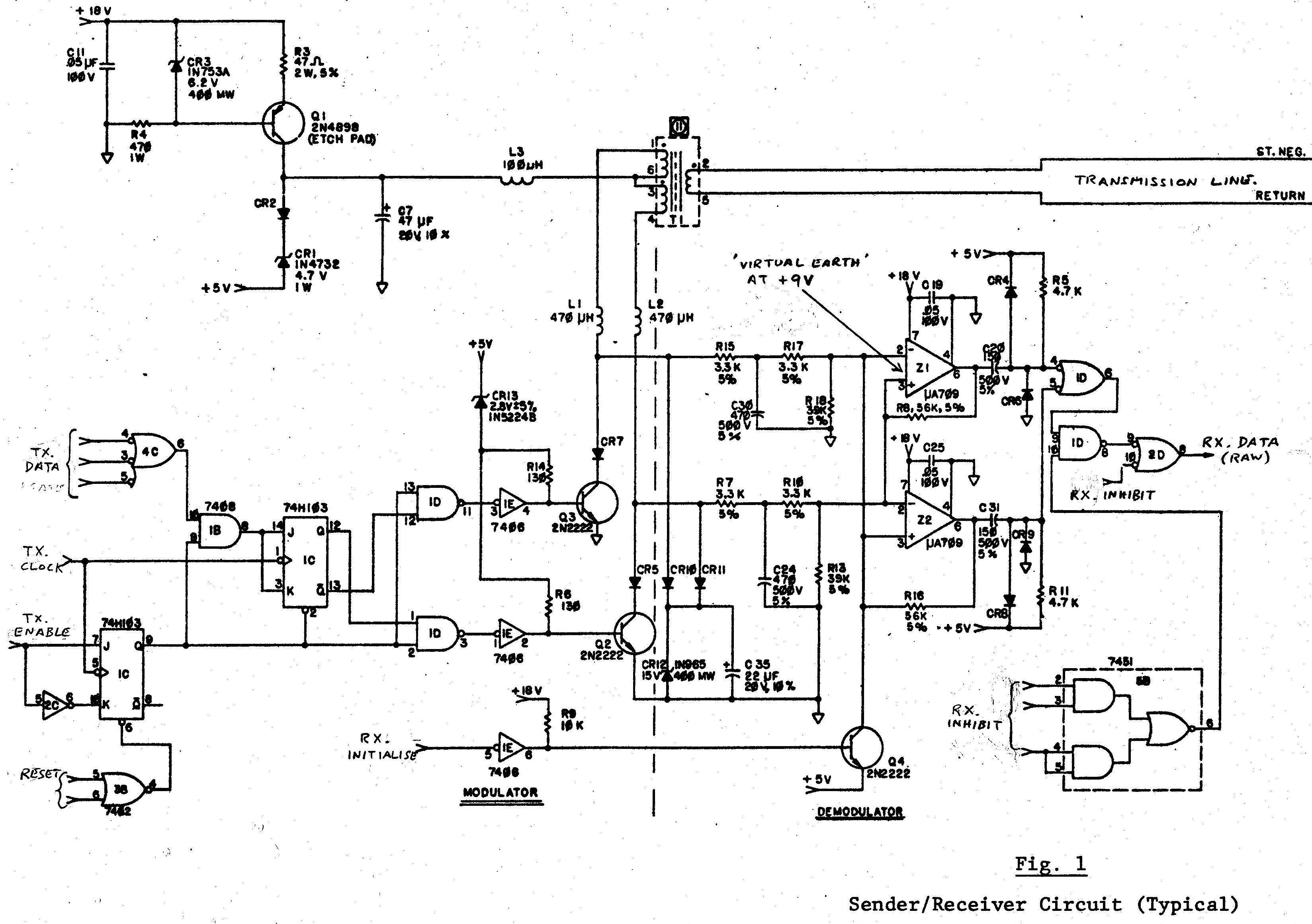
2. Sender/Receiver Circuit. (See Fig. 1)
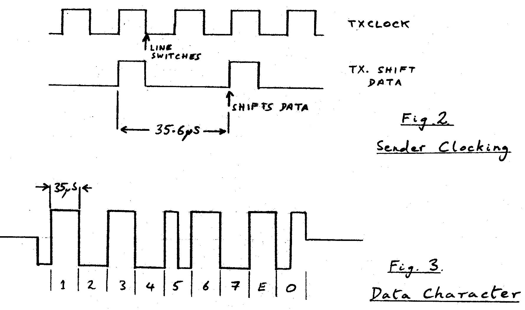
The sender operation is straightforward. Timing is shown in Fig. 2. The signal TXCLOCK
cycles at twice the desired bit rate (56.25kHz, i.e. 450kHz divided by 8). A sourced current of l20mA is
switched to either side of the line-coupling transformer, Tl.
When receiving, the sender is isolated by CR5 and CR7. Amplifiers Zl and Z2 are connected as Schmitt
triggers, each having switching levels of + and -lV, referred to the centre tap of Tl. Before receiving
data, the circuit is initialised by a short negative pulse at RXINITIALISE, which sets the Schmitts into
standard initial conditions. Signal-pulse trains always commence with a departure from 0V to -2.5V at ST.NEG,
which is ignored, since the Schmitts are already in the corresponding polarity. The following positive
transition fires the Schmitts, defining the start of Bit 1. Data (if enabled) appears at RXDATA as a
train of short +ve pulses.
3. Data Formats.
3.1 Data Character (See Fig. 3)
All data-bit trains begin with a -ve transition from 0V (on the ST-NEG data line). Data characters comprise
9 bit-cells, each of 35.6m S duration. The start of each bit-cell is marked by a
transition, and the presence of an additional transition in the centre of the cell defines a "1" bit. Bits
1 to 7 represent the data character, in standard ASCII notation ("DLE" - 0x10 - is shown in Fig. 3). Bits
8 and 9, designated as "E" and "O", are parity bits, computed as even parity over the even and odd data bit
positions, respectively.
3.2 Acknowledge Burst (1).
This pulse-train (referred to as ACKl) is used by either the IOC or a terminal, to acknowledge receipt of a
character. The ACKl signal comprises a train of 2 or more "1" bits. It may be of indefinite length, and is
used on output instructions to synchronise the IOC to slow peripherals. The device receiving ACKl must not
send more characters until ACKl has terminated. Typically, the next character may be sent some 60mS after
ACKl terminates. ACKl itself should commence some 60mS after the line returns to zero after the end of
the data character.
3.3 Acknowledge Burst (2).
ACK2 is issued only by the IOC, never by a terminal. It indicates the receipt of a data character (as does
ACKl), and further indicates that the input operation is finished (i.e. that the programmed count is exhausted).
ACK2 typically comprises two "1" bits, followed by nine "0"s. Two or more zeros will define ACK2, although the
string may be of indefinite length, to achieve synchronisation.
4. Polling.
When no device is selected (see below), the IOC continuously polls device 0 for a Load
request, and devices 0 to 9 for Service requests.
4.1 Poll Sequence.
A poll sequence comprises a DLE character, followed by a poll character. Devices do not normally send ACKl
in response to a poll sequence. The DLE character will unconditionally deselect all devices.
| Bits 765 |
Meaning |
| 000 |
Not Used |
| 001 |
Not Used |
| 010 |
Service request offer |
| 011 |
Load Request offer (device 0 only). |
| 100 |
Read Data. |
| 101 |
Write Data. |
| 110 |
Read Control (sets Load state). |
| 111 |
Write Control. |
4.2 Poll Character Format.
The poll character is used as follows. Bits 4 - 1 give the polled device address (0 - 9);
while bits 7 - 5 decode as shown at the right.
4.3 Response.
A device never makes a response to the DLE character, or to any poll character which does not address that
device.
When addressed, a peripheral may answer Load Requests or Service
Requests by an ACKl sequence, to initiate the corresponding action in the CPU. Load Request will cause
the CPU to issue a Read Control instruction, which will set the "LOAD" indicator (if any)
on the selected device (always Channel 0).
Select operations (bit 7 set) must be answered by ACKl within 100mS, or the instruction will be aborted,
with CC-4 set (absent device).
5. Input (READ) Operations.
5.1 Selection.
The required input device is selected via a poll/select sequence (see above). The poll character will specify
Read or Read Control, and must be answered by ACK1 (typically after 60mS).
5.2 Data Transmission.
About 100mS after ending ACKl, the terminal should send the first data character.
If no live character is ready, a DEL character may be sent (this will not be stored by the CPU). Characters
must be of the System-10 restricted character set (ASCII columns 2, 3, 4 or 5). After some 60mS, the CPU will
reply with ACKl if another character is expected, or ACK2 if no more are expected.
The terminal may force premature termination of the input operation by sending a US character, which the CPU
will not store, and will acknowledge with ACK2.
| Bit |
Value |
Condition Code set |
| 7 |
"0" |
|
| 6 |
"1" |
|
| 5 |
"0" |
|
| 4 |
"0" |
|
| 3 |
FAULT\ |
(CC-4: overflow) (NB. inverted). |
| 2 |
FLAG |
(CC-3: high) |
| 1 |
ERROR |
(CC-l: low) |
5.3 Status Character.
Following the ACK2 from the IOC, the terminal is required to send a Status character, which will post
Condition Codes to the program. As for data input, DEL characters may be used to pad out until the status
character is available. Such DEL's, and the Status character itself, will be answered with ACK1 from the
IOC.
The format of the Status character is shown at the right.
The Status character is answered by ACKl, and the input operation is terminated. The IOC
will then commence a new Poll sequence, testing for Load and Service Requests.
6. Output (WRITE) Operations.
6.1 Selection.
The device selection sequence is as for Input operations. After the terminal sends ACKl to the Select
character, the IOC will (after about 100m S), send the first data character.
6.2 Data Transmission.
Each character sent by the IOC is (if valid) answered by AGK1. Inter-character delays, in both directions,
are typically 60mS. Write Control operations send characters in the ASCII Control
format (Columns 0 and 1 of the ASCII character table).
Finally, the IOC sends an EOT character, defining the end of the string. The terminal responds with ACKl,
before proceeding to the Status sequence.
6.3 Status Character.
A Status character (or the first padding DEL) should be sent about 150m S
after the ACKl reply to the IOC's EOT. Inter-character delays during the DEL sequence will be about
60m S. The Status character has the same format as for Input operations.
7. Error Control.
An ACK sequence will normally be sent about 60m S after the end of the character it
acknowledges. No ACK will be sent to a character of invalid parity, or framing errors.
If ACK is not received within about l00m S, the character will be re-transmitted
(by the IOC or the terminal) up to 4 times. After 5 unsuccessful attempts, the terminal should 'lock up' ,
until another poll sequence is received, which should reset it. This will cause the IOC to abort the operation,
setting CC-4 to the program (persistent transmission error).
Service Requests
A user terminal was provided with a service request key, which set a condition-code bit.
When it wished, the program could execute a "Branch on Service Request" instruction, which would
branch if the user had pressed this key.
Load-Local
Terminals had an Online/Local switch, and a Load key.
If Load and Local were pressed simultaneously, the terminal responded
to a Load poll from the CPU. This effectively jammed a
Read Control instruction into Locations 9990-9999, which was then executed.
This instruction caused 10 characters to load into 0000-0009, which were then executed as an
instruction. So a crashed program could be escaped by pressing Load/Local, then entering
P0PP051000, for example.
Boot-up
The following question would be put to students in training seminars: I press Load/Local,
then simply press Enter, with no data typed. What happens?
The Load/Local initiates a Read Control for 10 characters, however Enter is pressed
at once, so no data is supplied. Read instructions fill the unused buffer with spaces,
in this case. However, this is a Read Control, so spaces are mapped to zeros.
Locations 0000-0009 are hence filled with zeros, and then executed as an instruction.
Now "0000000000" is a valid S-10 instruction: Read from disk drive 0, sector 0, to
memory 0000-0099. Instruction execution then continues from Location 0010, ie following
the disk read instruction (which has now been overwritten). This is, of course,
the system bootstrap. From Partition 0, this would reload LIOCS: other partitions
reloaded their own start-up code.
 Back to Home Page
 More System-10 Details